It is a bold statement to say, I am reinventing it, and obviously it cannot be taken seriously, but here is a concept design of the simplest and most used mechanical device, also considered one of the oldest inventions, the Wheel.
This concept is a mechanical approach, which in theory should function, and the next step is to test it.

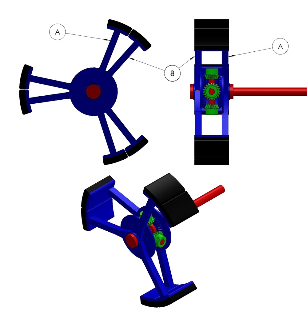
This wheel concept, I am calling “Differential Wheel”, because it uses the same mechanical principle as a differential drive in a car but here it is applied to the wheel itself. The wheel is segmented into two parts, there is no complete circle. Part A and Part B are as shown in the picture,each is made of three identical pads separated by 120 degrees angles. At anytime, one Part is in contact with the ground and thus is not totally free to rotate; it conducts the torque to the ground and drives the vehicle. The other part is not in contact with the ground and thus it is free to rotate; and moves faster to be ready to make contact with the ground. The animated video could be very helpful to show how this works.
To explain how this mechanism is actually functioning, the below picture brings more information. The torque comes in through the red shaft, which rotates and with it the green gears rotate around the shaft, these green gears are in contact with Part A (in Blue) on the left and Part B (Also in Blue) on the right. One Part is free to rotate so it does not carry torque but moves with high velocity, the other part is in contact with the ground and then is moves slower as it conducts the energy to the ground and moves the vehicle forward.

The design is of course not a final functional model and does not show any bearings that are essential to make it efficient. This is simply a concept model.
Opinions are welcomed. Do you think it could work ?
All those sudden shifts in momentum, energy, speed…looks like a inefficient, fatigue ridden nightmare.
Great intuition.
Needs significant modifications (such as mechanically constraining the freely rotating part from changing direction as it hits the ground ). But I see an opportunity to develop a wheel chair that can climb stairs.
The overall inertia is being maintained so the drive would probably be OK, if needing to be a little vibration tolerant. But do some calcs on the acceleration stresses the individual components see and I expect you will struggle to get to a useful speed.
You don't say what problem you are trying to solve with this device, which is a kinda critical oversight when you are looking for feedback as we will all jump to our own conclusions…! At first glance, I thought you were competing with the Tweel (www.michelintweel.com), but probably not?
Hello VinceS,
Thank you for the feedback.
The idea came to me when i was not looking for a problem to solve. So untill now it stands as a solution without a problem. I think a problem could come up somewhere in time and this design could be a solution for it.
I am grateful for the mechanical feedback I am recieving on the deisgn even though it lacks a focus on a specific application.
thank you again.
Thank you Anirudh,
It needs improvement for sure. I am putting it public on forums so that people interested can improve the design.
Hello Boothby171,
I agree with you, the design needs improvement to be usefull in application. I am putting it public so that interested people can take this "Broken" idea and maybe make a better working version.
re mech design, it is a fairly simple process, although I would have to admit to being a little rusty! Two areas for initial attention – the easier one is to figure out what is happening as a load on the sun gears. First problem is to decide if one gear has a substantial load or they are shared. After wear shared will be fine, but really need some elasticity built in so the load is shared in a real world manufacturing environment or infant mortality will be your reality.
Once you have a shared load situation (or go with single) you can estimate a wheel mass and radius of rotation, getting the inertial mass => the force to accelerate it, once you know the time. The motion curve deserves thinking about as it is easy, but unrepresentative, to assume a steady ramp up and down in velocity from transport stage to transit stage.
When you put real numbers in there I suspect you won't like the size of gears you would need to transmit the likely forces… Obviously the crown to spoke connection has to transmit these also, which is the next obvious area of weakness.
The other problem area is going to be the "reality gap" between what you have depicted and what will really happen. Mainly that as the dynamics of load transfer occur and one pad loads as the rearward one unloads, some highly surface friction dependent events are going to unfold. Especially if tangential forces come into the mix, or simple unevenness. Yay, another infant mortality zone!
Don't take these comments as disparaging. It is a physical world and physical laws are always going to be reality, when you find out / how adapt to them is all that is up for grabs. What you have dreamed up here is a great example of lateral thinking. Despite it being apparently unusable.
I have used this core concept to put a really cheap differential on a go-kart once (30 years ago) but soon found the advantage it gave me is I could beat anyone in the rain, but I hated racing in the rain! I put the design in the public domain somewhere for anyone that had ducks feet.
So what COULD this concept be used for? Is it the latest macadamia nut cracker? Doubt it, but it is a novel concept and worthy of kicking down the street a little. Is a stair climbing wheel chair idea feasible? The inertial forces would be of little consequence, but thinking about the many ways this stair-wheel could be popped out I think stability and safety would never get a guernsey as you only need one clutzy operator to expire using the product and it is engineer mortality that gets you!. Keep thinking and good luck, applications are king…
Thank you for the detailed opinion VinceS.
I agree with both point of weakness and i think springs can be added to adjust the relative motion between spokes.
For friction impact , maybe the goemetry of the pads that touch the ground and touch other pads can be adjusted to minimize that or maybe lateral contact with bearings would be a better design.
Again it will end up an even more complicated design, and for what ? I agree it might not have a usefull application as far as i can think of now.
It is a thinking exercise , it might lead to something at some point.
As a MechE, this kind of thing is kind of interesting. On the downside, it seems like it has all the advantages of a 6 spoked wheel with the disadvantage of all the nasty dynamics in handing off between the 'feet', especially at high speeds. In general, it is easier to make things more complicated, but hard to make them better, so from that perspective I'm not that interested.
However, it would be possible to actuate the arms (spokes?) of the wheel or otherwise passively adjust them. So then maybe there's a space in rough terrain management that would typically be navigated by something with treads (caterpillar design). OTOH, that's typically on heavy equipment. So perhaps on light duty rough terrain type applications where a drone would not be feasible? Like maybe remote exploring a narrow but deep cave? A treaded device would have difficulty navigating significant elevation changes compared to something with these on the front and traditional rear wheel drives on the back.
I also like that you can easily change the feet material. Or at least you could design it modularly. So that a person could put on feet geared towards their specific application. I suppose while it's not as fuel efficient as a wheel, it would also be more fuel efficient than a flying drone, depending slightly on the duty cycle.
Anyways, those are some random ramblings, probably should go back to work.
It is very interesting, but when you only need a "clock" you don't need to create the Antikythera Mechanism. – I am the inventor that patented the original 'custom spinner wheel' TRU-Spinners® aka Wheel Enhancers / Spun for 15 minutes / Another embodiment was a triple-spinner that have 27 different spinning modes.- I am telling you this to let you know I have been 'in and out' – 'up and down' and all round with bearings and many wheel inventions.- I see the "Means & Function" but why? – What purpose does it serve? – You don't need to reply as I am just mentioning these points for you to consider. – I see this as 'not' serving as, or replacing an automotive wheel, but rather an application of sorts in possibly manufacturing, of 'what' I do not know. – Just telling you how it 'strikes me'.- Best of luck! – Best regards, J.D.Gragg
Maybe it is time to bring back paddle wheel steamers.. I think some marine applications may be a useful thought train..
Say Rami, Royden may be onto something there. I have never studied it, but undoubtedly the issue with efficiencies on paddle wheelers is about all the lateral movement, and therefore wasted frictional forces, involved in having the water move in front of the blade. With this system the blade is clear and can carry a full "cup" of water. And existing paddle wheel drives would be good for it. The load sharing and flexural issues mostly vanish along with driveline vibration.
So, do the fluid dynamics calcs and see if you are actually going to get something useful with this design, eg 20% more thrust. Then do the market research and see if the efficiency gain is cash in the bank and they would pay to change out their existing wheels to this new design. See, applications are king!
Thank you , nice ideas.
Potential applications 🙂
Hey Gragg, you have a good point.
I am not trying to replace a car wheel , this design is not efficient for that.
Thx VinceS ,
I think i got what i needed from this so far, which is other engineers to think about it and see where it could be usefull.
I will proceed and make a 3D printed model and test it, and I will add it to this article. (I am currently writing my master thesis, so this wheel is not my priority now.)
See sci fic ATV on Damnation Alley 1977 movie has similar pattern but uses rubber wheels
This comment has been removed by the author.
Thx , I just looked at the pictures.
It has 3 wheels attached to thre spokes and the structure holding the wheels does not rotate. It is a cool design though especially for 1977.
It will produce jerks due to sudden impact from the other parts. Which introduce friction and lags on the gears. If it is using in automobile, may be you can use no of parts and you can reduce impact and increase uniform motion.
At best it is less good than a wheel.